Government of Newfoundland and Labrador

Digital Government and Service NL

Motor Registration

Air Brake Manual Newfoundland and Labrador

Air Brake Manual

FOREWORD

This manual has been compiled to assist you in your understanding of the basic functions of the air brake system.

Study of this manual, along with practical instruction, is recommended to those who are preparing for the completion of the air brake examinations, as administered by the Motor Registration Division.

The diagrams provided are for instructional purposes and are not to be interpreted as regulations.

Study questions are included to test your understanding of the subject.

Credit for the compiling of this manual goes to the British Columbia Motor Vehicles Branch. Their manual is used by a number of jurisdictions in Canada and the United States.

Air Brake Manual Newfoundland and Labrador

Brakes and Braking

  • Heat, Energy, Traction, Friction
  • Speed, Weight, Distance
  • How We Obtain Power
  • Stopping Distance
  • Section Summary Questions
Air Brake Manual Newfoundland and Labrador

Heat, Energy, Traction, Friction

For a vehicle to move along the highway, an internal combustion engine must convert its HEAT ENERGY into mechanical ENERGY. This mechanical ENERGY goes from the engine to the driving wheel tires by means of a system of connecting rods, shafts and gears. The final factor that moves the vehicle is the amount of TRACTION its tires have on the road surface. TRACTION is the ability of a tire to grip the road surface on which it rolls. The vehicle’s acceleration rate depends on the power the engine develops and the amount of TRACTION the tires have on the road surface.

FRICTION is the force which resists movement between two surfaces in contact with each other. To stop a vehicle, the brake shoe linings are forced against the machined surfaces of the brake drums, creating FRICTION. This FRICTION produces HEAT.

The engine converts the ENERGY of HEAT into the ENERGY of motion. The brakes must convert this ENERGY of motion back into the ENERGY of HEAT. The FRICTION between brake drums and linings generates HEAT, while reducing the mechanical energy of the revolving brake drums and wheels. The heat produced is absorbed by the metal brake drums, which dissipate the heat by passing it off into the atmosphere. The amount of heat the brake drums can absorb depends on the thickness of the metal of which they are made. When enough FRICTION is created between the brake linings and the drums, the wheels stop turning; but the final factor that stops the vehicle is not the brakes, but the TRACTION between the tires and the road surface.

If an engine of 200 horsepower accelerates a vehicle to 100 km/h in one minute, imagine the power needed to stop this same vehicle. Not only that, but the vehicle might have to be stopped in an emergency, in as little as six seconds (just 1/10 of the time it took to reach 100 km/h).
Accelerating vehicle illustration

To stop the vehicle in 1/10 of the time it took to accelerate would require a stopping power of 10 times the acceleration power – the equivalent of approximately 2,000 horsepower. If the vehicle had six wheels, each wheel would have to provide 1/6 of the braking power. If one or two of the wheels had brakes that were not properly adjusted, the other wheels would have to compensate, and that might be more than the brakes were constructed to stand. Excessive use of the brakes would then result in a buildup of heat greater than the brake drums could absorb and dissipate. Too much heat would result in brake damage and possible failure.

Brake lining illustration

Most brake linings operate best at around 250°C and should not exceed 425°C. It’s important to understand that the power needed to stop generates heat which could ruin the brakes.

Air Brake Manual Newfoundland and Labrador

Speed, Weight, Distance

The distance required to stop a vehicle depends on its speed and weight, in addition to the factors of energy, heat and friction. The brake power required to stop a vehicle varies directly with its weight and the ‘square’ of its speed. For example, if the weight is doubled, the stopping power must be doubled to be able to stop in the same distance. If the speed is doubled, the stopping power must be increased four times to be able to stop in the same distance. And, when weight and speed are both doubled, the stopping power must be increased eight times to be able to stop in the same distance.

For example, a vehicle carrying a load of 14,000 kgs down a steep grade at 16 km/h is brought to a stop in a distance of 30 meters by normal application of the brakes. If this same vehicle carried 28,000 kgs down the same grade at 32 km/h, it would require eight times the braking power to stop the vehicle in 30 meters. This would be more braking power than the brakes could provide. No vehicle has enough braking power when it exceeds its limitations.

Air Brake Manual Newfoundland and Labrador

How We Obtain Power

A. MECHANICALLY

Mechanical advantage breaking system illustration

Braking systems use devices to gain a mechanical advantage. The most common device for this purpose is leverage. Look at this simple lever system;

Fulcrum diagram

A lever is placed on a pivot called the fulcrum. As the distance from A to C is four feet, and from C to B is one foot, the ratio is four to one (4:1). Power has been multiplied by the leverage principle. If a 100 lb. downward force is applied at point A, then the upward force at point B is 400 lbs.

This is the result of the mechanical advantage of leverage.

Lever diagram

Compare the Points A, C, B to the previous lever diagram.

B. USE OF AIR

Force can also be multiplied by the use of air to gain a further mechanical advantage. Everyone has felt the power of air on a windy day. Air can be compressed (squeezed) into a much smaller space than that amount of air normally would occupy. For instance, air is compressed in tires to support the weight of a vehicle. The smaller the space into which air is squeezed, the greater the air’s resistance will be to being squeezed. This resistance creates pressure, which is used to gain mechanical advantage.

If a constant supply of compressed air were directed through a pipe that was one inch square, and if a one inch square plug were placed in the pipe, the compressed air would push against the plug. Holding a scale against the plug would register how many pounds of force were being exerted by the air against the plug.

Compressed air illustration

If the scale registered 10 pounds, for example, then it could be said the force was 10 pounds on the one square inch surface of the plug. This would be 10 pounds per square inch (P.S.I.).

The more the air in the supply tank has been compressed, the greater the force that would be exerted on the face of the plug.

C. LEVERAGE & AIR PRESSURE

In actual operation, pipes are round and plugs are diaphragms of flexible material acting against push rods. If compressed air of 120 pounds per square inch (P.S.I.) acts on a diaphragm of 30 square inches, 3,600 lbs. of force is produced (120 x 30). Apply this force to a push rod to move a six-inch slack adjuster operating a cam and the total force equals 21,600 inch pounds torque (3,600 x 6), or 1,800 foot pounds torque (21,600 ÷ 12). It requires 25 – 30 foot pounds of torque to tighten the wheel on a car. This comparison illustrates the power obtained from using mechanical leverage and air pressure combined.

 Illustration of power obtained

Air Brake Manual Newfoundland and Labrador

Stopping Distance

In addition to the above factors, a driver must understand what is meant by the term ‘stopping distance’. Stopping distance consists of three factors:

Driver’s reaction time + brake lag + braking distance.

REACTION TIME: The time it takes from the moment a hazard is recognized to the time the brake is applied, approximately 3/4 of a second. (Reaction time is often called ‘thinking time’.)

BRAKE LAG: The time the air takes to travel through a properly maintained air brake system, approximately 4/10 of a second.

BRAKING DISTANCE: The actual distance the vehicle travels after the brake is applied until the vehicle stops.

(The distance depends on the ability of the lining to produce friction, the brake drums to dissipate heat and the tires to grip the road.)

The professional driver never takes the brakes for granted. The braking system must be tested and the adjustment checked before placing the vehicle into service. The professional understands the braking system, realizes the capabilities and limitations and learns to use them to the best advantage.

Heavy vehicles require powerful braking systems that are obtained by use of mechanical leverage and air pressure. Brakes must be used keeping in mind the heat generated by friction. If the heat becomes too great, braking effectiveness will be lost. The heavier the load and the faster the speed, the greater the power needed to stop.

Stopping distance is also affected by the driver’s reaction time, brake lag and braking distance. The professional driver is well aware that the vehicle, even with properly adjusted brakes, will not stop as quickly as a passenger vehicle.

Stopping distances illustration

Air Brake Manual Newfoundland and Labrador

Section Summary Questions

1. What is the final factor that will determine if the vehicle will move?
2. What is the final factor that will determine if the vehicle will stop?
3. How is the heat dissipated that is generated by the brakes?
4. If one set of brake shoes are poorly adjusted, what effect could it have on the remaining sets of brake shoes in the system?
5. What is meant by the term ‘FRICTION’?
6. If the weight of the vehicle is doubled, how many times must the stopping power be increased?
7. If both weight and speed of the vehicle are doubled, how many times must the stopping power be increased to be able to stop in the same distance?
8. If the speed of the vehicle is doubled, how many times must the stopping power be increased to be able to stop in the same distance?
9. What is compressed air?
10. What does the abbreviation ‘P.S.I.’ stand for?
11. If 40 P.S.I. is exerted against a diaphragm of 30 square inches in area, what is the total pounds of force that could be exerted?
12. ‘Brake lag’ is approximately 4/10 of a second in a well maintained, single circuit brake system. What is meant by ‘brake lag’?
13. What is meant by the following terms? ‘reaction distance’ – ‘braking distance’ – ‘stopping distance’.


Section 1 of this manual has explained that it is possible to gain a mechanical advantage through the use of levers and that air under pressure can be used to gain a mechanical advantage. Section II will explain how air under pressure can be used to operate the air brakes of a vehicle.

Piping diagrams have been kept simple in order to be easily understood. The piping arrangements found on vehicles in actual use on the highway might differ somewhat from the illustrations in this manual.

The diagrams in this manual ARE NOT to be interpreted as regulations for, or specifications of, air brake systems.

Air Brake Manual Newfoundland and Labrador

Compressor

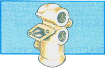
Compressed air is the means of transmitting force to an air brake system. The source of the compressed air is the compressor. A compressor is designed to pump air. Air pumped into a tank will result in pressurizing the air, as was explained previously in this manual.

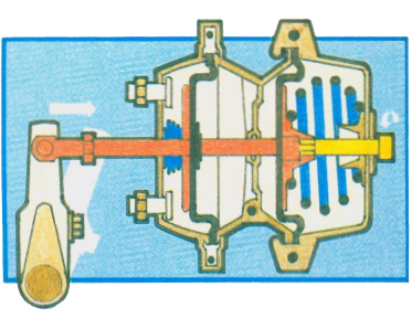
A piston type compressor operates on a similar principle to that of the intake and compression strokes of an engine.

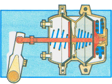
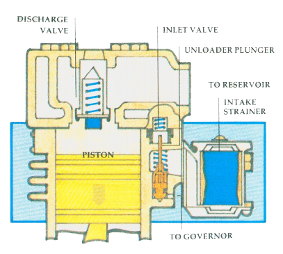
INTAKE STROKE: The downward stroke of the piston creates a lower pressure within the cylinder than the atmospheric pressure outside the compressor. This causes air to flow past the inlet valve (which the atmospheric pressure has opened) into the cylinder.

Intake Stroke illustration

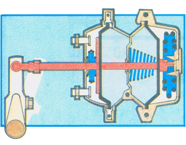
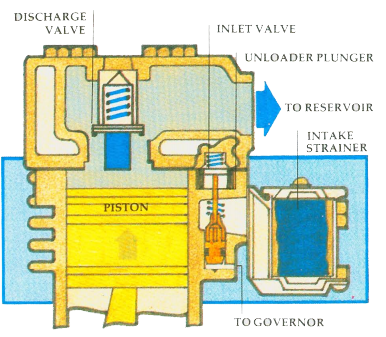
COMPRESSION STROKE: The upward travel of the piston compresses the air in the cylinder. The rising pressure cannot escape past the inlet valve (which the compressed air has closed) and as the piston nears the top of the stroke, the pressurized air is forced past the discharge valve and into the discharge line leading to the reservoir.

Compression Stroke illustration

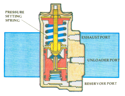
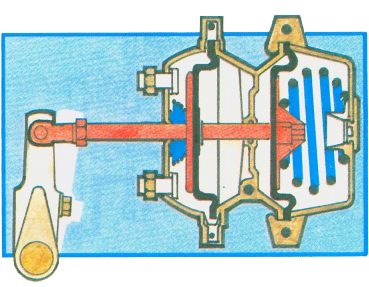
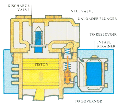
UNLOADING: When sufficient pressure has been built up, the compressor goes into an ‘unloading’ stage. The unloader plunger holds the inlet valves off their seats until pressure drops to the pre-set cut in pressure which is regulated by the governor.

Unloading compressor illustration

The compressor is driven by the vehicle’s engine, by either belts and pulleys or shafts and gears. In vehicles which the compressor is driven by belts, the belts should be checked regularly for cracks and tension. Belt adjustment is usually checked by pressing with a finger midway between the pulleys. A greater distance between the pulleys will affect the amount of permissible slack. If the belts become too slack, they could slip, and the compressor will not achieve its maximum efficiency. While checking the drive belts also check the compressor for broken mounting brackets or loose mounting bolts.

The compressor is in constant drive with the engine. Whenever the engine is running, so is the compressor. It is usually lubricated from the engine lubrication system. Some compressors are self-lubricating and require regular checks of lubricant levels.

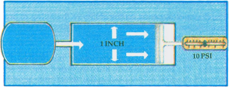
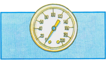
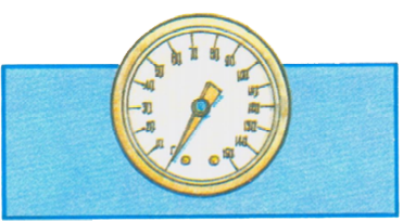
There are periods of time when it is not necessary for the compressor to pump air. A common pressure in an air brake system is from a low of 85 P.S.I. to a high of 105 P.S.I. Some systems operate between 105 P.S.I. and 125 P.S.I. Minimum pressure is approximately 20 P.S.I. below maximum pressure.

When the pressure has reached the system’s maximum, the compressor goes into an ‘unloading’ stage.

Most compressors have two cylinders. In the unloading stage, the inlet valves are held open, allowing the air to be pumped back and forth between the two cylinders, instead of compressing it. During the ‘unloaded’ stage, the compressor is able to cool.

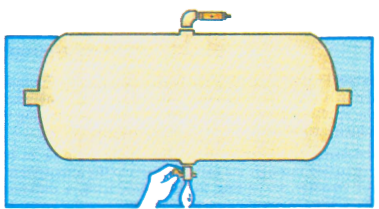
It is most important that the air in the air brake system be kept as clean as possible. Dirt in the system can cause trouble.

The air from the atmosphere that enters the compressor must first pass through a filter to remove any dust particles from the air. The air filter must be cleaned regularly. A dirty filter will restrict the flow of air into the compressor, reducing its efficiency. Some vehicles have the inlet port of the compressor connected to the air cleaner of the vehicle’s engine.

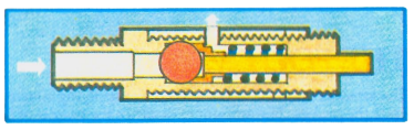
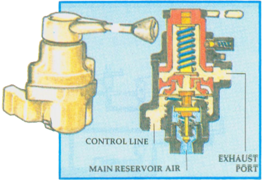
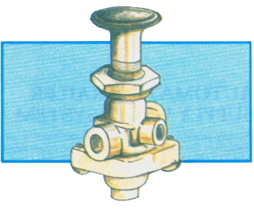
A governor controls the minimum and maximum air pressure in the system. As the compressor is in constant drive with the engine, the governor’s job is to ‘unload’ the compressor when the desired pressure is reached. The governor does this by directing air pressure to the inlet valves of the compressor, holding them open when pressure in the system reaches its maximum. When the pressure in the system drops by approximately 20 P.S.I., the governor allows the inlet valves to close, returning the compressor to its pumping stage.

Pumping stage compressor illustration

Air Brake Manual Newfoundland and Labrador

Reservoirs

Reservoirs or tanks hold a supply of compressed air. A safety valve protects them from being over pressurized and bursting. The safety valve protects the air brake system from an excessive buildup of air pressure. The valve consists of a spring loaded ball that allows air to exhaust the reservoir pressure into the atmosphere. The valve’s pressure setting is determined by the force of the spring. A safety valve is normally set at 150 P.S.I. If the pressure in the system rises to approximately 150 P.S.I., the pressure would force the ball off its seat, allowing the pressure to exhaust through the exhaust port in the spring cage. When reservoir pressure is sufficiently reduced (to approximately 135 P.S.I.), the spring will force the ball back onto its seat, sealing off the reservoir pressure. Not all safety valves have a manual release feature as shown in the diagram below.

If the safety valve has to relieve the pressure, it indicates that the governor or compressor requires service or repair. This should be done by a qualified mechanic.

Safety valve illustration

IMPORTANT! SAFETY VALVE ADJUSTMENTS MUST NOT BE TAMPERED WITH. ONLY QUALIFIED MECHANICS SHOULD SERVICE SAFETY VALVES.

Reservoirs or tanks are also equipped with drain cocks to drain off any moisture. When air is compressed, it becomes heated. The heated air cools in the reservoir, forming condensation. Oil leaking past the piston rings of the compressor mixes with this moisture to form a sludge in the bottom of the reservoir. If allowed to accumulate, this sludge (water and oil) would enter the braking system. An excess of water in the system causes trouble with valves and other parts. In winter, water in the system may freeze, causing malfunction of valves or brake chambers.

Reservoir illustration

To minimize the amount of water collection, all tanks must be drained daily. Under extreme conditions, tanks may have to be drained more than once a day. Park the vehicle on a level surface, set the parking brake, block the vehicle’s wheels, open drain cocks fully. Allow all air pressure to escape, which will then permit the moisture collected in the tank to drain. Some tanks have more than one compartment and each compartment has its own drain cock. Briefly opening the valve just to allow some of the air to escape DOES NOT drain the moisture.

Some reservoirs are equipped with automatic reservoir drain valves (spitter valves). These may be drained manually by pushing up on a rod on the underside of the valve.

Most vehicles are equipped with more than one reservoir. This gives the system a larger volume of main reservoir air. As the first tank collects more of the moisture and oil from the compressor, it is called the ‘wet tank’. The second tank is usually further from the compressor and so collects drier or cleaner air. This tank is called the ‘dry tank’.

Reservoirs vary in size. The size of the tanks to be installed on a vehicle depends on the number and size of the brake chambers. Brake chambers with a 30 square inch diaphragm will obviously require a larger volume of reservoir air than those equipped with 20 square inch diaphragms.

Air Brake Manual Newfoundland and Labrador

Foot Valve

The foot-operated valve is the means of applying air to operate the brakes. The amount of distance the treadle of the foot valve is depressed by the driver determines the amount of air pressure that will be applied, but the MAXIMUM APPLICATION WILL NOT EXCEED THE PRESSURE IN THE RESERVOIR. Releasing the foot valve treadle releases the brakes.

Foot-operated valve illustration

When the driver applies the brakes, depressing the treadle part way, the foot valve will automatically maintain the application air pressure, without the driver having to adjust the pressure of his foot on the treadle.

Releasing the treadle allows the application air to be exhausted through the exhaust ports to the atmosphere. Air treadles are spring loaded, producing a different ‘feel’ from hydraulic brake application.

Air Brake Manual Newfoundland and Labrador

Brake Chambers and Slack Adjusters


Brake chamber illustration

A brake chamber is a circular container divided in the middle by a flexible diaphragm. Air pressure pushing against the diaphragm causes it to move away from the pressure, forcing the push rod outward against the slack adjuster. The force exerted by this motion depends on air pressure and diaphragm size. If a leak occurs in the diaphragm, air is allowed to escape, reducing the effectiveness of the brake chamber. If the diaphragm is completely ruptured, brakes become ineffective.

Front brake chamber illustration

Front brake chambers are usually smaller than rear brake chambers because the front axles carry less weight than the rear axles. A brake chamber is usually mounted on the axle, near the wheel that is to be equipped for braking. Air pressure is fed through an inlet port. The air pushes against the diaphragm and the push rod. The push rod is connected by a clevis and pin to a crank arm type lever called a ‘slack adjuster’. This converts the pushing motion of the push rod from the brake chamber to a twisting motion of the brake camshaft and ‘S’ cams. When the air is exhausted, the spring in the brake chamber returns the diaphragm and push rod to the released position.

As indicated by its name, the slack adjuster is also the means of adjusting the ‘slack’ or free play in the linkage between the push rod and the brake shoes. This slack occurs as the brake linings wear. If the slack adjusters are not adjusted within the limitations, effective braking is reduced and brake lag time is increased. If too much slack develops, the diaphragm will eventually ‘bottom’ in the brake chamber. If this condition is allowed to occur, the brakes will not be effective at all.

Slack adjuster illustration

Slack adjuster with worm adjusting gear illustration

The diagram illustrates a common type of slack adjuster, showing the worm adjusting gear. When the brakes are fully applied, the angle between the push rod and the arm of the slack adjuster should be no more than 90 degrees (a right angle) On this type of slack adjuster, the adjusting worm bolt is turned until the brake linings touch the drums and then backed off, normally 1/4 to 1/2 a turn. A locking device, which may be a spring loaded collar over the head of the adjusting bolt, must be depressed when the wrench is slipped over the bolt head. Some slack adjusters use a spring loaded internal check ball to lock the adjustment. The more often the driver checks the ‘slack’, the less the probability of brake failure Vehicles rarely ‘lose’ their brakes because of loss of air; it is usually a loss of adjustment.

Front brake chamber illustration

Some systems have automatic slack adjusters which adjust automatically to compensate for brake lining wear, thus maintaining the correct clearance between the brake lining and drum. Automatic slack adjusters must be checked regularly to ensure that correct adjustment is being maintained.

Automatic slack adjusters illustration

NOTE: Detailed brake adjustment procedures are outlined in Section VI.

The diagram below illustrates a common type of brake assembly used on truck rear axles and trailer axles. A front axle assembly has the brake chamber and slack adjuster mounted on the backing-plate because of the steering action.

Brake assembly illustration

Brake lining material is attached to the shoes. The material used depends on the braking requirements of the vehicle. Brake lining must give uniform output of brake effort with minimum fade at high temperature.

Fading or a reduction in braking effort occurs when the heated drums expand away from the brake linings. The brake linings also lose their effectiveness with overheating.

The twisting action of the brake cam shaft and ‘S’ cam forces the brake shoes and linings against the drums. The brake linings generate heat from friction with the brake drum surface.

The thickness of the drums determines the amount of heat they are able to absorb and dissipate to the atmosphere. Drums worn thin will build up heat too quickly. Dangerously undependable brake performance will result from distorted drums, weak return springs, improper lining, poor adjustment, or grease or dirt on the lining.

Drums must never be turned or worn beyond the manufacturer’s specification.

Air Brake Manual Newfoundland and Labrador

Wedge Type Brake

Here is another example of a type of brake assembly used on some air brake equipped vehicles. The action of the brake chamber push rod forces a wedge shaped push rod between the brake shoe rollers. This forces the brake shoe lining against the brake drum.

Brake chamber illustration

The vehicle may be equipped with a single chamber or two chambers on each wheel, depending on the vehicle’s size and style.

These brakes may be equipped with a self-adjusting mechanism or with a manual ‘star wheel’ adjuster. The ‘star wheel’ adjustment is made with the vehicle jacked up, to ensure that the brake linings do not drag. Manual adjustment of wedge type brakes is usually a job for a mechanic.

"star wheel" adjustment illustration

Spring brakes added to these units are of the piggy-back type.

Air Brake Manual Newfoundland and Labrador

Disc Brakes

Disc brake illustration

The air activated heavy truck disc brake is similar in principle to the disc brake used on passenger vehicles. Air pressure acts on a brake chamber and slack adjuster, activating the brakes. For light truck and passenger car braking systems, hydraulic pressure is used. Instead of the cam or wedge used in conventional heavy truck drum brakes, a power screw is used. A ‘power screw’ works like a C-clamp, so that the lining pads exert equal force to both sides of the disc or rotor. Some types of disc brakes have a built-in automatic adjuster. Disc brakes that require manual adjustment have adjustment specifications different from conventional ‘S’ cam braking systems. ALWAYS CHECK MANUFACTURER’S SPECIFICATIONS BEFORE ADJUSTING.

Air Brake Manual Newfoundland and Labrador

Section Summary Questions

  1. What are the five basic components of an air brake system?
  2. What are two standard main reservoir pressures for the operation of a vehicle’s air brakes?
  3. At what pressure should the governor cause the compressor to return to its pumping stage?
  4. How is a plugged air filter likely to affect the compressor?
  5. What causes moisture to form in the air brake system?
  6. When is the compressor able to accomplish most of its cooling?
  7. How are most compressors lubricated?
  8. How often should the main reservoirs be drained?
  9. Is it necessary to allow all the pressure to escape from the reservoir in order to remove the moisture and sludge which may have accumulated?
  10. What is the maximum pressure available for a full brake application at any given time?
  11. What will result if the brake drums are worn thin or turned too far?
  12. If the governor valve failed to ‘unload’ the compressor, what would be the result?
  13. What is the purpose of having more than one reservoir?
  14. What are two functions of the slack adjuster?
  15. Does the amount of slack in the brake linkages have any effect on the braking efficiency of the vehicle?
  16. What is the advantage of keeping the brake chamber push rod travel adjusted to minimum travel?
  17. What is the most common cause of loss of effective braking in an air brake system, loss of air pressure or loss of brake adjustment?
  18. Do automatic slack adjusters on ‘S’ cam brakes require checking?
  19. Can the adjustment on air operated disc brakes differ from ‘S’ cam type brakes?
  20. What occurs when drum brakes become overheated?
  21. What causes brake fade at high temperatures?
  22. What is the main function of the foot valve?
  23. Why does the ‘feel’ of an air operated foot valve differ from a hydraulic brake pedal?
  24. On what principle does a disc brake operate?
Air Brake Manual Newfoundland and Labrador

How The Basic System Works

  • Simple Air Break System
  • One Way Check Valve
  • Gauges
  • Brake Application Gauge
  • Low Pressure Warning
  • Wig-Wags
  • Stop Light Switch
  • Quick Release Valve
  • Relay Valve
  • Front Wheel Limiting Valve
  • Tandem Rear Axles
  • Parking Breaks (Spring Breaks)
  • Dual Control Valve and Reservoir System
  • Mechanical Release
  • Section Summary Questions
Air Brake Manual Newfoundland and Labrador

Simple Air Brake System

NOTE: ALL PIPING DIAGRAMS ARE USED TO ILLUSTRATE BASIC BRAKING PRINCIPLES ONLY AND DO NOT ILLUSTRATE ACTUAL AIR BRAKE SYSTEMS.

BASIC OPERATION PRINCIPLE

Air is pumped by the compressor (1) to the reservoir (2), which is protected from over pressurization by a safety valve (3). The governor (5) controls the pressure in the reservoir by governing the compressor. Air is available from the reservoir to the bottom of the foot valve (6). The driver pushes down the foot valve treadle and air pressure flows to the front and rear brake chambers (7, 8). The brake chamber push rods move the slack adjusters. The slack adjusters rotate the ‘S’ cams, forcing the brake shoes against the drums. This causes friction, which stops the vehicle. The driver releases the foot valve treadle, and the air in the brake chambers is allowed to exhaust through the foot valve, releasing the brakes.

Other valves are necessary to ensure smooth and efficient operation.

One way check valve diagram

Air Brake Manual Newfoundland and Labrador

One Way Check Valve

In the diagram below, two reservoirs are shown. This gives the system a larger volume of main reservoir air. The first tank in the system collects most of the moisture, and is referred to as the wet tank. The second tank is referred to as the dry tank. Reservoirs vary in size. The size of the tank or tanks installed on a vehicle depends on the number and size of brake chambers.

To prevent air from flowing back from the reservoirs to the compressor, a ONE WAY CHECK VALVE (9) is installed. This valve allows the air to flow in one direction only. The valve is spring loaded. Pressure at the inlet side overcomes the spring pressure and lifts the check valve ball, or disc, off its seat. Air passes through the valve to the outlet. When pressure at the outlet becomes greater than at the inlet, together with the spring pressure, the check device seats, preventing air from flowing back through the valve.

One way check valve illustration


Air Brake Manual Newfoundland and Labrador

Gauges

All vehicles are equipped with a pressure gauge (10) to indicate the amount of air pressure in the main reservoir system. This gauge is mounted in the cab, usually on the dashboard. Common operating pressures are 85 P.S.I. to 105 P.S.I. and 105 P.S.I. to 125 P.S.I., depending on the system. Monitoring the gauge will alert the driver to any unusual changes in pressure.
Pressure gauge illustration

Air Brake Manual Newfoundland and Labrador

Brake Application Gauge

An additional gauge can be installed on the dash to indicate the application pressure when the brakes are applied. This gauge can be piped to indicate the pressure of either a foot application or of a hand application. (Hand application will be explained later in the manual.)

Brake Application Gauge illustration

Air Brake Manual Newfoundland and Labrador

Low Pressure Warning

All vehicles equipped with air brakes must have a device to warn the driver if the air pressure in the system drops to a dangerous level.

Should the air pressure drop below approximately 60 P.S.I. due to overuse or leaks, the low pressure indicator switch (11) will turn on a red warning light on the dash, or cause a buzzer to sound. Some vehicles are equipped with both a light and a buzzer to warn the driver of a low air pressure condition.

Air Brake Manual Newfoundland and Labrador

Wig-Wags

There are two common types of ‘wig-wag’ low pressure warning devices that may be used. Both types will drop into the driver’s view when the pressure in the system drops below approximately 60 P.S.I. The automatic warning device will rise out of the driver’s view when the pressure in the system rises above 60 P.S.I. The manual reset type must be placed in the ‘out of view’ position manually and will not stay in place until the pressure in the system goes above 60 P.S.I.

Wig-wag" device illustration

Whichever warning system is used (buzzer, lights or wigwag) the driver MUST STOP their vehicle and find the cause of the air loss. The air pressure remaining in the system (approximately 60 P.S.I.) is enough for brake application if the driver acts promptly.

Air Brake Manual Newfoundland and Labrador

Stop Light Switch

Any driver following must be warned that speed is being reduced or the vehicle is being stopped. The STOP LIGHT SWITCH (12) is an air operated electric switch that turns on the brake lights on the rear of the vehicle when a brake application is being made.

Air Brake Manual Newfoundland and Labrador

Quick Release Valve

The application of the brakes in the simple system was described earlier. In such a basic system, when the driver releases the foot valve, it would be necessary for the air under pressure in the brake chambers to return back to the foot valve to release the brakes. This releasing action would be slowed in long wheel base vehicles, due to longer lines between the foot valve and the rear brake chambers. To allow the brakes to release quickly and fully, by discharging the application air near the brake chambers, a quick release valve (13) may be installed.

Quick release valve illustration

Air Brake Manual Newfoundland and Labrador

Relay Valve

The foot valve is usually located closer to the front wheels than to the rear wheels. The longer the distance from the foot valve to the rear chambers, the more time it will take (known as brake lag) before the rear brakes apply. To correct this condition on a long wheel base vehicle, a RELAY VALVE (14) is installed near the rear brake chambers. A larger diameter pipe is connected between the main reservoir and the relay valve. The air line from the foot valve to the relay valve now becomes a ‘control line’. (The air in the control line ‘dead ends’ at the relay valve.) When the foot valve is depressed, the air pressure in the control line acts on the top section of the relay valve, causing the relay valve to ‘relay’ reservoir air directly to the rear brake chambers through the larger diameter pipe. The pressure of the reservoir air delivered in this way will be the same as the control pressure delivered by the foot valve. Releasing the foot valve exhausts the control air to the relay valve, allowing it to cutoff the flow of reservoir air to the rear chambers, in turn exhausting the air in the brake chambers by the quick release feature of the relay valve.

Relay valve Illustration

Air Brake Manual Newfoundland and Labrador

Front Wheel Limiting Valve

For better steering control on a slippery road surface, it can be an advantage to reduce the braking effect to the front wheels. This can be accomplished by installing a control valve (15) in the cab, and a FRONT WHEEL LIMITING VALVE (16) on the front axle.

The driver places the control valve in the ‘normal’ position for dry road surfaces and the front braking application pressure is normal. On a slippery road surface, the driver may flip the control valve to the ‘slippery road’ position. In this position, the control valve will cause the LIMITING VALVE to operate. Application air pressure to the front wheels is then reduced to 50 per cent of the application air pressure being delivered to the rear brake chambers.

Limiting valve illustration

Some systems are equipped with an AUTOMATIC LIMITING VALVE (17).

Automatic limiting valve illustration

This valve will hold off brake application to the front wheels from zero to 10 P.S.I., depending on how it has been preset. Between the preset pressure and 40 P.S.I. of brake application, the reduction is approximately 50 per cent. Brake applications between 40 P.S.I. and 60 P.S.I. are reduced by less than 50 per cent. Brake applications over 60 P.S.I. are not reduced, full application is directed to the front wheels.

Front wheel limiting valve diagram

CHECK YOUR UNDERSTANDING

From the above diagram name each numbered component and briefly describe its function in the system. Write your answers on a separate sheet of paper.

Air Brake Manual Newfoundland and Labrador

Tandem Rear Axles

The air brake system discussed previously is that of a vehicle equipped with a single rear axle. The diagram illustrates an air brake system of a vehicle equipped with an automatic front wheel limiting valve (17), a quick release valve (13) and a tandem set of rear axles. Both axles of the tandem set are equipped with brakes.

A relay valve (14) is used to provide quicker application pressure to the tandem rear axles.

Tandem rear axle diagram

Air Brake Manual Newfoundland and Labrador

Parking Brakes (Spring Brakes)

Spring type parking brakes may be installed on an air brake equipped vehicle to ensure a reliable parking brake system. In the service brake system the brakes are held retracted by springs, and applied by air pressure. Spring type parking brakes are applied and remain applied WITHOUT AIR PRESSURE. The parking brake chambers are attached to the service brake chambers and operate the brakes through the same linkage. Therefore, the effectiveness of the parking brake depends on the service brake adjustment. A control valve (usually a square, yellow button) in the cab allows the driver to exhaust air out of the parking brake circuit to apply the brakes, or to repressure the circuit to release them. The system can also act as an emergency brake. Loss of air from the main system may automatically apply the brakes, depending on how the system is piped.

During normal driving, air pressure cages the spring, holding it ready for parking or emergency braking.

Spring ready for parking or emergency braking illustration

During normal service brake operation, the spring brake does not apply. Air pressure keeps the spring caged.

 Spring caged by air pressure illustration

Application of the dash control valve exhausts air from the spring brake chamber, causing spring force to activate the spring brake.

Activated spring brake illustration

PARKING BRAKE SYSTEMS

The installation of parking brakes and their piping arrangements into a vehicle air brake system will vary depending on the vehicle make.

Control valves will vary, depending on the manufacturer and type of piping arrangements.

Control valve illustration

This type of spring loaded valve requires that the driver push the button to release the parking brakes. This valve cannot be left in the released position below approximately 35 P.S.I. pressure in the main reservoir system. Any time the main reservoir pressure drops to approximately 35 P.5.I., this valve will exhaust automatically, placing the parking brakes into full application Similar types of spring loaded valves require that the driver pull the button out to release the parking brakes.

There is a single type of push-pull control valve in use that does not have an automatic release feature. To apply the parking brakes, the valve must be operated manually, even though the main reservoir pressure has been emptied.

USING THE PARKING BRAKES

Spring parking brakes diagram

The above diagram illustrates spring parking brakes (18) added to the brake chambers of the rear axle on the single unit vehicle. A control valve (19) is mounted in the cab. A supply line of reservoir air is piped from the dry tank to the control valve. Opening the control valve admits main reservoir air pressure to the parking brake units, releasing them.

Closing the control valve shuts off the supply of reservoir air pressure and exhausts the existing pressure in the parking brake units, thus applying the brakes.

SINGLE CONTROL PARKING BRAKE SYSTEM

The diagram below illustrates the use of a third tank with a single control, used on the rear axle of a single unit.

A control valve (19) is mounted in the cab. A supply line of reservoir air is piped from the dry tank through a one-way check valve (9) into a third tank. Closing the control valve shuts off the supply of reservoir air pressure and exhausts the existing pressure in the parking brake units, allowing them to apply the brakes. If the main reservoir air in the system should be emptied, the parking brakes will not apply, because the one-way check valve will isolate the pressure in the third tank. If the spring (parking) brakes are to be used to stop the vehicle, the driver will have to set the parking brakes manually with the cab control valve.

Single Control Brake System diagram

Air Brake Manual Newfoundland and Labrador

Dual Control Valve and Reservoir System

Some vehicles, such as buses, may also be equipped with an EMERGENCY RELEASE TANK (2).

In this system, if main reservoir pressure is lost, the spring brakes will automatically apply.

If the parking brakes have applied because of a loss of main reservoir air, the driver can draw reserve air from the emergency release tank to release the parking brakes. A dual parking brake control (19) is used together with the emergency release tank. The driver must press on the emergency release button. Releasing the emergency release button will automatically allow the parking brakes to re-apply.

Emergency release tank illustration

The emergency release would only be used to move the vehicle from an undesirable location, if the parking brakes had been applied due to a low main reservoir air condition.

CAUTION: Parking brakes should be in the released position before making a service brake application. A full brake application, made when the parking brakes are applied, can compound the force exerted on the slack adjusters and linkage, which could result in damage or brake failure. Compounding is the combination of two forces; the force applied by the spring brakes and the force applied by the service brake.

NOTE: Spring type brakes are primarily a parking brake, but in the event of loss of main reservoir air, they can assist in stopping the vehicle. How quickly they will stop the vehicle depends on such factors as:

  • The weight and speed of the vehicle;
  • The steepness of the grade;
  • The spring force of the spring brakes which have been installed; and,
  • The adjustment of the service brakes.

Dual Control diagram

Air Brake Manual Newfoundland and Labrador

Mechanical Release

Some types of parking brakes can be released mechanically by ‘winding them off’ or ‘caging’ them. A bolt, which runs through the centre of the chamber body, is turned to compress the spring. It may be necessary to first remove a lock plate and stud, to gain access to the head of the bolt. Other types have a plug which must first be removed and a bolt inserted. In some cases, a special wrench is required. Instruction on how to ‘cage’ is usually on the body of the parking brake. If all air is lost and the vehicle has to be moved, the parking brake can be released by winding them off. DO NOT wind off the spring brakes completely. Leave enough brake force to stop the vehicle after it has been moved. Always block the wheels when caging the parking brake spring. Caging means the brakes are being released.

"Caged" parking brake illustration

WARNING!
Parking brakes should never be disassembled without first compressing the spring with a wind-off bolt. These springs are under extreme pressure and could cause serious personal injury if disassembly is attempted by anyone not experienced in servicing these units. Disassembly is a job for a mechanic.

Air Brake Manual Newfoundland and Labrador

Section Summary Questions

  1. How can the driver tell how much air pressure there is in the main reservoirs?
  2. What must the driver do when a low pressure warning system activates?
  3. What is the purpose of a quick release valve?
  4. What is the purpose of a relay valve?
  5. What is the purpose of using a larger diameter pipe between the main reservoir tank and the relay valve?
  6. If the front axle limiting valve is in the ‘slippery road’ position, and the foot valve is depressed to make a brake application of 30 P.S.I., how much pressure will be applied in the front brake chambers?
  7. How is the reservoir protected from over pressurization?
  8. What stops pressurized air from flowing back into the compressor from the dry tank?
  9. At what pressure will the low pressure warning device activate?
  10. How is ‘brake lag’ to the rear wheels minimized?
  11. When should a driver use the front wheel limiting valve?
  12. What is meant by ‘compounding’ the brakes?
  13. Why are spring brakes a reliable type of parking brake?
  14. How are parking brakes held in the released position?
  15. What are the functions of the cab-mounted parking brake control valve?
  16. Will parking brakes apply ‘automatically’ in all braking systems?
  17. What is the reason for releasing the parking brakes before making a full brake application test?
  18. What is the purpose of an emergency release reservoir tank in a parking brake system?
  19. How can some types of parking brakes be released without the use of air pressure?
  20. What is the danger of disassembling a parking brake unit?
Air Brake Manual Newfoundland and Labrador

Trailer Systems

A. MECHANICALLY

Mechanical advantage breaking system illustration

Braking systems use devices to gain a mechanical advantage. The most common device for this purpose is leverage. Look at this simple lever system.

Fulcrum diagram

A lever is placed on a pivot called the fulcrum. As the distance from A to C is four feet, and from C to B is one foot, the ratio is four to one (4:1). Power has been multiplied by the leverage principle. If a 100 lb. downward force is applied at point A, then the upward force at point B is 400 lbs.

This is the result of the mechanical advantage of leverage.

Lever diagram

Compare the Points A, C, B to the previous lever diagram.

B. USE OF AIR

Force can also be multiplied by the use of air to gain a further mechanical advantage. Everyone has felt the power of air on a windy day. Air can be compressed (squeezed) into a much smaller space than that amount of air normally would occupy. For instance, air is compressed in tires to support the weight of a vehicle. The smaller the space into which air is squeezed, the greater the air’s resistance will be to being squeezed. This resistance creates pressure, which is used to gain mechanical advantage.

If a constant supply of compressed air were directed through a pipe that was one inch square, and if a one inch square plug were placed in the
pipe, the compressed air would push against the plug. Holding a scale against the plug would register how many pounds of force were being exerted by the air against the plug.

Compressed air illustration

If the scale registered 10 pounds, for example, then it could be said the force was 10 pounds on the one square inch surface of the plug. This would be 10 pounds per square inch (P.S.I.).

The more the air in the supply tank has been compressed, the greater the force that would be exerted on the face of the plug.

C. LEVERAGE & AIR PRESSURE

In actual operation, pipes are round and plugs are diaphragms of flexible material acting against push rods. If compressed air of 120 P.S.I. acts on a diaphragm of 30 square inches, 3,600 lbs. of force is produced (120 x 30). Apply this force to a push rod to move a six-inch slack adjuster operating a cam and the total force equals 21,600 inch pounds torque (3,600 x 6), or 1,800 foot pounds torque (21,600 ÷ 12). It requires 25 – 30 foot pounds of torque to tighten the wheel on a car. This comparison illustrates the power obtained from using mechanical leverage and air pressure combined.

 Illustration of power obtained

LINKS

  • Glad Hands
  • Application Line
  • Hand Valve and Two Way Check Valve
  • Tractor Protection
  • Automatic Trailer Supply Valve System
  • Trailer Supply Valve
  • Tractor Protection Valve
  • Tractor and Trailer Unit Coupled
  • Charging the Trailer System
  • Brake Application – Foot Valve
  • Brake Application – Hand Valve
  • Emergency Applications
  • Service Line Rupture
  • Supply Line Rupture
  • Loss of Main Reservoir Air
  • Manually Operated Trailer Supply Valves
  • Section Summary Questions
Air Brake Manual Newfoundland and Labrador

Glad Hands

It can be assumed that the system illustrated up to this point is the air brake system of a truck unit. If a trailer was coupled to this unit, the brakes of the trailer would have to be operated from the tractor.

The following diagram shows the piping of a unit, similar to the tandem axles of the truck unit. The trailer has a single axle equipped with brake chambers.

A ‘TEE’ has been installed in the application line between the foot valve and the truck axle system. A line has been connected from this tee to the trailer by a set of couplers called ‘GLAD HANDS’ (20).


This term refers to the coupling device used to connect the service and supply lines of the trailer to the truck or tractor. These couplers have a snap lock position, and a rubber seal prevents air from escaping.

Glad hands illustration

Before connection is made, couplers should be clean and free of dirt and grit. When connecting the glad hands, start with the two seals together and the couplers at a 90 degree angle to each other. A quick snap downwards will join and lock the couplers. Vehicles equipped with ‘dead-end’ couplers should have these protection plates in use whenever the vehicle is used without a trailer. This will prevent water and dirt from entering the coupler and lines.

If the unit is not equipped with dead-end couplers, the glad hands of the service line can be locked to the glad hand of the supply line to keep water and dirt from entering the unused lines. The cleaner the air supply is kept, the less chance of brake problems.

Glad hands and lines should also be secured to prevent the line from bouncing off the vehicle. This could seriously damage the couplers.

Glad hands diagram

Air Brake Manual Newfoundland and Labrador

Application Line

The application line is referred to as a SERVICE LINE. In this simple system, used for an example, the driver depresses the foot valve treadle, and application air will be delivered to the tractor brake chambers and to the trailer brake chambers. When the driver releases the foot valve treadle, the application air to the trailer brake chambers must return to the foot valve to be exhausted to the atmosphere.

In this example system, there would be disadvantages:

If the trailer broke away from the tractor, the trailer would have no brakes.

If the service line parted or ruptured, the trailer brakes could not be applied, and the application air would be lost from the tractor if a brake application were made.

If the air in the main reservoirs were lost, there would be no way to apply the brakes of the tractor or the trailer.

The trailer brakes cannot be applied independently from the tractor, and there is no way to set the trailer brakes when coupling to the tractor.

The application and release of the trailer brakes would be slower than those of the tractor.

These disadvantages are overcome by the addition of the lines and valves discussed in the following pages.

Air Brake Manual Newfoundland and Labrador

Hand Valve and Two Way Check Valve

To provide a brake application to the trailer unit only, a HAND VALVE (21) and a TWO-WAY CHECK VALVE (22) are piped into the system.

The purpose of the hand valve is to allow the driver to control independently the amount of application air to be directed to the trailer brakes when a trailer brake application is being made. It also provides a method of applying the trailer brakes when coupling the trailer to the tractor.

The purpose of a two-way check valve is to allow control of the trailer brake by use of the hand or foot valve. This valve EXHAUST will permit air to flow from the source which is supplying the MAIN RESERVOIR AIR PORT higher application pressures.

Trailer only brake application diagram

HAND OPERATED VALVES

For trucks that are intended to pull trailers, the hand operated valve is added to the air brake system to operate the trailer brakes. This valve allows the driver to apply the trailer brakes independently of the tractor. The amount of application air pressure delivered depends on the amount the valve is opened by the driver. Some valves must be closed by the driver; others will close automatically from any open position. Valves may be of a type that will remain in the full open position only, or they may be equipped with a locking device that will hold them in the desired position.

NOTE: The hand valve is NOT to be used for parking, as air may bleed off if the engine is stopped or the hand valve moves to the released position.

Hand valve illustration


A TWO-WAY CHECK VALVE

This valve allows air to be directed to one delivery pipe from either of two sources. A two-way check valve allows the source applying the higher pressure to shift the shuttle so that the higher pressure will be directed to the delivery or ‘service line’. This valve is used between the foot operated valve and the hand operated valve, for the purpose of independently controlling the trailer brakes.

The driver has applied the brakes by using the foot valve. Application air is directed to the brake chambers of the tractor AND to the trailer brakes through a two-way check valve (22). The shuttle has shifted to the low pressure side, closing off any air flow toward the hand valve side. The hand valve (21) is in the closed position and equal pressure is being applied to the brake chambers of the tractor and the brake chambers of the trailer.

Two-way check valve illustration

Two-way check valve diagram

In this diagram, with the foot valve released, and the hand valve (21) opened, application air is directed from the hand valve through the two-way check valve (22), to the brake chambers. The two-way check valve in this application has shifted to the low pressure side, closing off any air flow toward the foot valve side.

Two-way check valve (higher pressure) diagram

The amount of application pressure through the hand valve depends on the amount that the valve is opened by the driver. But it cannot exceed main reservoir pressure.

Any time a trailer brake application is made by use of the hand valve, the driver may depress the foot valve treadle. If the foot valve application is of a higher pressure than that of the hand valve, the two-way check valve will shift to the lower pressure side, allowing the higher pressure to be directed to the tractor and trailer brakes.

If, during a foot valve application, the driver makes a higher pressure hand valve application, the two-way check valve will allow the higher hand valve application to be directed to the trailer brakes.

Regardless of whether the trailer brakes are applied independently by means of the hand valve, or together with the tractor brakes by the use of the foot valve, the maximum application pressure can only be the same as, or slightly less than, MAIN RESERVOIR PRESSURE.

Air Brake Manual Newfoundland and Labrador

Tractor Protection

A tractor protection system is added to prevent total loss of air from the tractor if the trailer breaks away, or if the connecting air lines between tractor and trailer become separated or ruptured. The tractor protection system consists of two valves added to the tractor system: the TRACTOR PROTECTION VALVE (23), and the TRAILER SUPPLY VALVE (24). Other names for the trailer supply valve are ‘trailer parking control’ and ’emergency valve’.

There are two types of trailer supply valves in use. The most common is a spring loaded valve that, after being opened manually, is held open by air system pressure. This device is called an automatic trailer supply valve.

Some tractors have a manual trailer supply valve. These may be a toggle type switch or a push/pull type.

The tractor protection valves vary in outward appearance, depending on make and model, but all perform the same function: protecting the tractor air supply.

Air Brake Manual Newfoundland and Labrador

Automatic Trailer Supply Valve System

The diagram below illustrates that the main reservoir air is piped from the main reservoir lines to the trailer supply valve (24). The tractor protection valve (23) is fed by two lines, one from the trailer supply valve (24) and one from the two-way check valve (22). Leading off from the tractor protection valve are two lines, each with a glad hand coupler. These two lines are referred to as the SERVICE LINE and the SUPPLY LINE.

In the diagram, the upper line is the service line and the lower line is the supply line.

To understand the function of the trailer supply valve and the tractor protection valve in the system, it is important to understand how they operate.

 Service and Supply Line Diagram

Air Brake Manual Newfoundland and Labrador

Trailer Supply Valve

This valve (usually a red octagonal button) is mounted in the cab of the vehicle, easily accessible to the driver. The driver opens the valve by pushing or pulling the button, depending on the type used.

Trailer supply valve illustration

Opening the valve permits main reservoir pressure to flow through the valve. This pressure is piped to the tractor protection valve and the supply line glad hand. The valve is spring loaded, and will be held in the open position when sufficient pressure is reached. If the pressure drops to a range of between 45 – 20 P.S.I., the valve will shut automatically by spring pressure, opening the exhaust port. The driver can close the valve manually to uncover the exhaust port.

Air Brake Manual Newfoundland and Labrador

Tractor Protection Valve

This is an example of a tractor protection valve, which is usually mounted on the cab or chassis of the tractor.

 Tractor protection valve illustration

The diagram below illustrates a tractor unit equipped with a trailer supply valve (24) and a tractor protection valve (23). The trailer is not coupled and the tractor is being operated as a single unit. The driver has not opened the trailer supply valve (24) and the hand valve (21) is closed.

Tractor unit diagram

Tractor unit diagram depicting brake application with the foot valve

In the diagram above, the driver has made a brake application with the foot valve (6), and application air is being delivered to the tractor brake chambers. The two-way check valve (22) has shifted to the low pressure side, allowing application air in the control line to reach the tractor protection valve (23).

There is no air loss from the tractor through the disconnected glad hands (20).

If the driver, by mistake, applied the hand valve (21), with the trailer disconnected, the application air directed to the tractor protection valve would also be dead-ended. Again, no air loss would occur if the trailer supply valve (24) is in the closed position.

Tractor unit with disconnected glad hands diagram

Air Brake Manual Newfoundland and Labrador

Tractor and Trailer Unit Coupled

Trailer coupled to tractor diagram

In the diagram above, the trailer has been coupled to the tractor and the service and supply lines of the units have been coupled by using glad hands.

The trailer unit has a reservoir (2) installed. This tank will provide a volume of air near the trailer chambers for normal or emergency braking. The tank is equipped with a draincock.

A RELAY EMERGENCY VALVE (25) is mounted on the trailer reservoir. This valve can also be mounted directly on the trailer frame near the brake chambers. The relay emergency valve serves three main functions in the system:

  1. The RELAY part of the valve relays air from the trailer reservoir to the trailer brake chambers during a brake application. This part of the valve operates like the relay valve previously discussed. It also provides a quick release of the trailer brakes.
  2. The EMERGENCY part of the valve directs trailer reservoir pressure to the trailer brakes, causing an emergency application (dynamiting). This action will occur automatically in the event of ruptured or parted air lines between tractor and trailer, or loss of air from the main reservoir system. The driver may operate the cab-mounted trailer supply valve (24) to cause an emergency application of the trailer brakes.
  3. The relay emergency valve has a one-way check valve that stops air in the reservoir from going back to the source of the supply.
Air Brake Manual Newfoundland and Labrador

Charging the Trailer System

In the previous diagram, the compressor has raised the main reservoir pressure to maximum.

In the next diagram, the driver has opened the trailer supply valve (24) to allow the main reservoir air pressure to be directed through the tractor protection valve (23) to the trailer. The air pressure passes through the relay emergency valve (25) to the reservoir on the trailer. Pressure will build up in the trailer reservoir to the same pressure as the main reservoirs on the tractor. This is known as ‘charging’ the trailer system. The trailer supply valve will remain in the open position when the pressure has built up to between 20 and 45 P.S.I., depending on the make.

"Charging" the trailer system diagram

Air Brake Manual Newfoundland and Labrador

Brake Application – Foot Valve

Brake application with foot valve diagram

The diagram above illustrates the air flow action during a brake application being made with the foot valve (6). The application air has applied the tractor brakes and the trailer brakes together. As previously explained, the two way check valve (22) has shifted, and application air is being directed through the tractor protection valve (23) to the service line.

This control pressure moves through the service line to act on the relay emergency valve (25). This control pressure will cause the relay emergency valve to direct reservoir air from the trailer tank to the trailer brake chambers (26). This will be of the same P.S.I. as the control pressure, which was the P.S.I. of the application air by the foot valve. In such a system, brake lag time has been minimized.

Release of the foot valve treadle stops the flow of application air. The relay portions of the valves return to their original positions, stopping the flow of air pressure. The exhausting ports of the valves exhaust the air pressure from the brake chambers, releasing the brakes.

In this system, the brakes of both units can be released quickly.

Air Brake Manual Newfoundland and Labrador

Brake Application – Hand Valve

The driver can use the hand valve (21) to apply the trailer brakes. The air flow is illustrated in the next diagram. The tractor protection valve (23) and relay emergency valve (25) are operated by the application air, as was explained in the foot valve application.

Closing the hand valve will release the brakes by closing off application air. The air pressure in the chambers and lines will exhaust, also as explained in the previous foot valve application.

CAUTION: TRAILER BRAKES MUST NOT BE USED TO HOLD A PARKED VEHICLE THAT IS LEFT UNATTENDED. LOSS OF PRESSURE WILL RESULT IN LOSS OF BRAKES! ALWAYS SET THE PARKING BRAKE.

Air flow using hand valve diagram

Air Brake Manual Newfoundland and Labrador

Emergency Applications

Trailer Breakaway diagram

A TRAILER BREAKAWAY would result in a separation of the service line and the supply line. The sudden loss of air pressure in the supply line will trigger the relay emergency valve (25), which causes the trailer reservoir (2) to dump its air directly to the trailer brake chambers (26). This places the trailer brakes into emergency application.

The loss of pressure in the supply line also causes the trailer supply valve (24) to automatically shift to the close position.

The tractor brakes are operable without air loss because the tractor protection system has isolated the tractor.

The trailer brakes will remain applied until either the pressure in the trailer reservoir and lines is drained off, or the supply line is repaired and the system is recharged.

Air Brake Manual Newfoundland and Labrador

Service Line Rupture

If the service line is ruptured or disconnected, no action will take place until a brake application is made.

In this diagram, the service line has ruptured and the driver has made a brake application with the foot valve (6).

The application air is directed to the control line through the tractor protection valve (23). Rupture of the service line will result in the escape of air pressure, causing a loss of pressure in the tractor system. This pressure drop will cause the tractor protection system to close off, exhausting the supply line to the trailer. This will cause the trailer brakes to go into an emergency application.

The trailer brakes may be released by opening the trailer supply valve (24) to recharge the trailer system. A further application of the foot valve or hand valve would again trigger an emergency application.

NOTE: Depending on the type of tractor protection system used, the air loss from the tractor will stop immediately or it will blow down to between 45 and 20 P.S.I. and then shut off.

Ruptured service line diagram

Air Brake Manual Newfoundland and Labrador

Supply Line Rupture

Supply line rupture diagram

A rupture of the supply line, or an uncoupling of the supply line glad hands, will result in a drop of pressure in the supply line between the trailer supply valve (24) and the relay emergency valve (25). This will trigger the emergency action of the relay emergency valve, placing the brakes into emergency application. As in the previous examples, the trailer supply valve (24) will shift to the closed position.

The operation of the tractor brakes will not be affected if the tractor protection system is in working condition.

The relay emergency valve (25) must be the no bleed-back type, so no air is lost from the trailer.


Air Brake Manual Newfoundland and Labrador

Loss of Main Reservoir Air

Rupture of the compressor discharge line would result in loss of pressure from the wet tank. When the pressure in the wet tank (2) of the tractor unit falls below the warning level, due to a compressor failure or excessive leakage on the tractor, the warning devices (11) will start to operate. In the diagram, the one-one check valve (9) has prevented the main reservoir air in the dry tank from escaping back to the wet tank and the ruptured line.

There is sufficient reservoir air pressure in the dry tank for a limited number of brake applications to stop the vehicle before the parking brakes are activated. This will depend on how the parking brakes are piped.

Ruptured compressor discharge line diagram

Closed tractor protection system diagram

If this pressure is lowered to approximately 45-20 P.S.I. the tractor protection system will close automatically, placing the trailer brakes into an emergency position.

The tractor protection system described in this manual is an example of a vehicle equipped with a type of cab mounted trailer supply valve (24) that will close automatically when the pressure in the supply line drops below 45-20 P.S.I. The valve may also be closed manually.


Air Brake Manual Newfoundland and Labrador

Manually Operated Trailer Supply Valves

Some vehicles are equipped with a different type of cab mounted trailer supply valve, which must be operated manually by the driver. It has two positions: NORMAL and EMERGENCY.

The tractor will be equipped with a tractor protection valve, and the trailer unit with a relay emergency valve, as in the previous system.

The functions of the trailer supply valve, tractor protection valve and the relay emergency valve will be similar to those illustrated. An important difference is that the trailer supply valve must be shifted to the EMERGENCY position manually.

CHARGING THE TRAILER SYSTEM:

The driver places the trailer supply valve in the NORMAL position and main reservoir air will be directed to the trailer reservoir.

TRAILER BREAKAWAY:

The supply line will cause the trailer brakes to dynamite. To prevent air loss from the tractor, the driver must shift the trailer supply valve to the EMERGENCY position. Otherwise the tractor air pressure will bleed down and hold at 45-20 P.S.I.

RUPTURED SERVICE LINE:

As in the example, no action will occur until a brake application is made. Application of the brakes with a ruptured service line will result in a loss of pressure in the system. When the main reservoir pressure drops to between 45-20 P.S.I., the trailer brakes will dynamite.

RUPTURED SUPPLY LINE:

As in the example, the loss of supply pressure will cause the trailer brakes to dynamite. To prevent air loss from the tractor the driver must shift the cab-mounted trailer supply valve to EMERGENCY. Otherwise the tractor air pressure will bleed down and hold at 45-20 P.S.I.

If a slow loss of main reservoir air occurs, when the supply line pressure drops to between 45-20 P.S.I., the relay emergency valve will cause the trailer brakes to dynamite.

MANUAL DYNAMITING OF TRAILER:

Any time the driver shifts the cab-mounted trailer supply valve to the emergency position, and the trailer system is charged, the trailer supply valve will exhaust the supply line, dynamiting the trailer brakes.

The trailer brakes will remain applied only as long as air pressure remains within the trailer system. How long the air in the system will hold the brakes applied depends on how airtight the system is. As a safety precaution, parked trailers should always be blocked to prevent a possible runaway.

To move a trailer that has been parked with the brakes in an emergency application it is necessary to charge the system to release the trailer brakes.

Air Brake Manual Newfoundland and Labrador

Section Summary Questions

  1. What is the purpose of a two-way check valve?
  2. Why should the glad hands be protected when not in use?
  3. How can a driver control the trailer brakes independently?
  4. What are three ways of testing the emergency application of the trailer brakes?
  5. Should the hand valve of a tractor trailer unit be used for parking?
  6. What is the main purpose of the tractor protection valve?
  7. What is the main purpose of the trailer supply valve?
  8. Name three functions of the relay emergency valve.
  9. Describe the function of the supply line.
  10. Describe the function of the service line.
  11. What will occur if the supply line ruptures?
  12. What will occur if the service line ruptures?
  13. What will occur if a brake application is made with a ruptured service line?
  14. If the foot valve and the hand valve are operated at the same time, can the application pressure be greater than the reservoir pressure?
Air Brake Manual Newfoundland and Labrador

Dual Air Systems

  • A Simple Dual Circuit Air System
  • Combination Truck and Trailer
  • T-75 Off-Highway System, Single Unit
  • L-75 Off-Highway System, Combination with Schedule X Trailer
  • Schedule SX, Off-Highway Trailer with Spring Brake
  • Section Summary Questions
Air Brake Manual Newfoundland and Labrador

A Simple Dual Circuit Air System

More and more heavy duty vehicles on the road today are using a Dual Circuit Air System. The system has been developed to shorten stopping distances and reduce brake failures. At first glance, the dual system might seem complicated, but if you understand the basic air system described so far, and if the dual system is separated into its basic functions, it becomes quite simple.

As its name suggests, the dual system is two systems or circuits in one. There are different ways of separating the two parts of the system. On a two-axle vehicle, one circuit operates the rear axle and the other circuit operates the front axle. If one system has a failure, the other system is isolated and will continue to operate.

NOTE: ALL PIPING DIAGRAMS ARE USED TO ILLUSTRATE BASIC DUAL CIRCUIT PRINCIPLES ONLY AND ARE NOT TO BE INTERPRETED AS REGULATIONS FOR, OR SPECIFICATIONS OF, DUAL AIR BRAKE SYSTEMS.

Dual Circuit Foot Valve illustration

In the illustration below, air is pumped by the compressor (1) to the supply reservoir (2) which is protected from over pressurization by a safety valve (3). Pressurized air moves from the ‘wet’ supply tank to the primary tank (green) and the secondary tank (red) through one-way check valves (9). At this point, the dual circuits start. Air from the primary tank is directed to the foot valve (6). Air is also directed from the secondary tank to the foot valve. The foot valve is similar to the one described earlier in the single circuit system, but has been divided into two sections (two foot valves in one). One section of this dual foot valve controls the primary circuit and the other section controls the secondary circuit. When a brake application is made, air is drawn from the primary tank (green) through the foot valve and is passed on to the rear brake chambers. At the same time, air is also drawn from the secondary tank (red), passes through the foot valve and is passed on to the front brake chambers. If there is an air loss in either circuit, the other circuit will continue to operate independently. Unless air is lost in both circuits, the vehicle will continue to have braking ability. The primary and secondary circuits are equipped with low pressure warning devices (11) and pressure gauges (10).

Dual circuit air system diagram

SIMPLE DUAL CIRCUIT SYSTEM WITH SPRING PARKING BRAKES

System using spring parking brakes diagram

When spring brakes are added to a dual circuit system the same type of dash control valve discussed previously is used. Blended air is used to supply the control valve (19). Blended air is air taken from the primary and secondary circuits through a two way check valve (22). With this piping arrangement the vehicle can have a failure in either circuit without the spring brakes applying automatically. Unless air is lost in both circuits the spring brakes will not apply.

SPRING BRAKES WITH MODULATOR VALVE

Spring type brakes in this system serve two purposes: first, as a parking brake, and second as an emergency system. If a failure occurs in the primary circuit (green), and a brake application is made, control air from the foot valve is directed to a spring brake modulator. As there is no supply air to maintain balance in the modulator valve, due to the primary circuit failure, the modulator valve then exhausts air pressure from the spring brake circuit. The amount of air released is equal to the amount of air applied by the foot valve. The release of air in the spring brake circuit causes the drive axle to brake using spring brake pressure (18). When the brake is released, supply air from the secondary circuit (red) returns the spring brakes to an off position. Brake applications can be repeated until all the air from the secondary circuit is lost but, as the air pressure drops below 85 P.S.I., the spring brakes will not return to the full off position. They will start to drag. At approximately 35 P.S.I., the spring brake control valve (19) on the dash exhaust the remaining air in the secondary circuit, and the spring brakes are fully applied. The only way the vehicle can be moved after all air is lost is to repair the damaged circuit and recharge the system, or cage the spring brake system.

Tandem tractors without steering axle brakes will have the primary and secondary systems split between the drive axles.

Spring brakes with modular valve diagram

Air Brake Manual Newfoundland and Labrador

Combination Truck and Trailer

The trailer system is supplied by blended tractor air taken from the primary and secondary circuit through a two way check valve as previously described.

The system is charged by opening the trailer supply valve (24), allowing air from the tractor to pass through the tractor protection valve (23) and the trailer spring brake valve (30) directly into the spring brake chambers (18). When air enters, the pressure protection part of the trailer spring brake valve opens, allowing the air to fill the trailer tanks.

When a brake application is made, blended control air acts on the relay valve (14) that releases air from the trailer tank to the brake chambers.

If the tractor breaks away from the trailer, the service and supply lines will be pulled apart. The sudden loss of air in the supply line will cause the tractor protection valve to close, preventing air from escaping out of either broken connection. The air supply in the tractor is sealed off and is available to control the tractor brakes. At the same instant, the sudden loss of air in the supply line causes the trailer spring brake valve to exhaust the air from the trailer spring brake chambers applying the trailer brakes. The trailer brakes cannot be released under these conditions unless the lines are recoupled and the trailer tanks recharged.

If only the supply line breaks between tractor and trailer, the same sequence of events will occur.

A break or rupture in the service line will not affect the trailer until a brake application is made. A loss of pressure in the tractor system will then result, causing the same emergency brake application described above. However, the driver will be able to release the parking brakes by releasing the foot valve, rebuilding air pressure and opening the trailer supply valve.

To apply the parking brakes, the control valve (19) is closed, causing a loss of pressure in the line that applies the spring brakes as described above.

The old and new tractor and trailer system are fully interchangeable, whether they are dual system or single circuit and whether they are systems with spring brakes or without.

NOTE: An air dryer (28) has been added to reduce the amount of moisture in the system.


Tractor and trailer system diagram

Air Brake Manual Newfoundland and Labrador

T-75 Off-Highway System, Single Unit

Air from the compressor is pumped into the supply tank (blue). Pressurized air moves from the supply tank to the primary tank (green), the secondary tank (red) and the front axle tank (brown) through one way check valves (9). When the air pressure reaches the governor cut-out setting (maximum 125 P.S.I.), the compressor cuts out and is in its cooling or ‘unloaded’ stage. When the air pressure drops approximately 20 P.S.I., the governor (5) returns the compressor to its pumping or ‘loading’ stage.

When a brake application is made by pushing down the dual foot valve treadle (6), air from the front axle circuit flows to the front axle relay valve and air from the primary and secondary circuits flows to the relay valves (14) at the rear axles. This control pressure on the relay valves causes the relay portion of the valves to open, relaying air pressure to the brake chambers. When the foot valve treadle is released, air pressure in the control lines between the foot valve and relay valves is released through the exhaust ports in the foot valve. Air pressure in the brake chambers is released through large exhaust ports in the relay valves.

Should either the primary or secondary SUPPLY circuit fail, the remaining circuit is isolated and continues to have braking ability.

When either of the primary or secondary SUPPLY circuit fails, braking on the front axle and one rear axle will not be affected due to the two way check valve (22) installed be tween the two service circuits.

Should a failure occur in the front axle circuit, the primary or secondary circuit will not be affected.

NOTE: A failure in any of the circuits will activate the low air warning system (11) and the driver MUST stop the vehicle to determine the cause. Should the air in the supply system drop to approximately 35 P.S.I., the spring brakes will apply

In this diagram the vehicle is equipped with a variable front wheel limiting valve (29). The application pressure delivered to the front axle is determined by the setting made by the driver.

To apply the spring parking brakes (18), the driver must move the control valve (19) to the ‘park’ position. This exhausts the control pressure from the spring brake relay valve (30), which then releases the air from the spring brakes, allowing them to apply.

To release the spring parking brakes, the driver must move the control valve to the ‘release’ position. This directs air to the spring brake relay valve, which supplies air pressure to the spring brakes, compressing or ‘caging’ the springs and releasing the brakes.

T-75 Off-highway system diagram

Air Brake Manual Newfoundland and Labrador

L-75 Off-Highway System, Combination with Schedule X Trailer

The L-75 tractor brakes are piped similar to the T-75 system. A low pressure governor (31), a dump valve (32), a hand valve (21), a two-way check valve (22) and a relay type tractor protection valve (33), have been added. In this system, when air pressure rises to approximately 60 P.S.I., the low pressure governor opens, allowing air pressure to close the emergency dump valve. When maximum air pressure is reached, the governor unloads the compressor.

To fill the trailer tanks, the driver must open the trailer supply valve (24) until the trailer supply line gauge (34) shows over 50 P.S.I. The trailer supply valve will then remain open on its own, keeping the trailer tanks at the same pressure as the tractor tanks.

When a brake application is made with the foot valve, air flows through a two-way check valve (22) to the control port on the tractor protection relay valve (33), which relays air pressure from the supply line to the service line. The service pressure line relays air from the trailer tanks through the relay emergency valves (25) to the trailer brake chambers.

When the brakes are released, air pressure in the service line is exhausted through the exhaust port in the tractor protection relay valve. Air pressure in the trailer brake chambers is exhausted through a large exhaust port in the relay emergency valves. This action, both in application and release, is simultaneous on tractor and trailer.

L-75 Off-highway system diagram

To apply the trailer brakes only, or for a higher brake application on the trailer than on the tractor, the driver applies hand valve (21), air from the tanks flows through the hand valve into a double-check valve (22), to the tractor protection relay valve (33). Brakes on the trailer are then applied and released as described above.

If necessary, the trailer brakes can be ‘dynamited’ by closing the trailer supply valve. This shuts off the air supply from the tanks and simultaneously exhausts the supply line into the atmosphere. Loss of air pressure in the supply line causes the trailer’s relay emergency valves to dump full reservoir pressure into the brake chambers.

The trailer system will provide a rapid application and release of the trailer brakes as each axle has its own air tank and relay emergency valve.

If a brake chamber or air line ruptures on one axle, the other axle continues to have braking ability for emergency stops.

The L-75 tractor system has the same air loss safety features as the T-75.

Air Brake Manual Newfoundland and Labrador

Schedule SX, Off-Highway Trailer with Spring Brake

The SX trailer brake system is piped similar to the Schedule X system. Both systems provide air loss safety features. A one-way check valve (9), a third tank (2), a spring brake control valve (19), two four-line two-way check valves (35) and four spring brakes (18) have been added.

SX trailer brake system diagram


The addition of spring brakes serves two functions. It provides a method of securing the trailer when parked and acts as an emergency brake for the trailer axle that has lost its supply reservoir pressure. The trailer spring brakes are held off or caged by trailer supply reservoir pressure.

If the trailer has lost all supply reservoir pressure and must be moved, the spring brakes may be released by opening the spring brake control valve (19) located at the rear of the trailer. This directs air from the isolated third tank to release the spring brakes. The spring brakes may be reset by closing the spring brake control valve. Care should be taken when moving the trailer as the service brakes will not apply.

NOTE: Regulation piping diagrams for off highway air brake systems are listed in Appendix I.

Air Brake Manual Newfoundland and Labrador

Section Summary Questions

  1. What is the basic principle of the dual circuit system?
  2. What valve is used to protect the primary circuit from the secondary circuit?
  3. In a simple dual circuit system, will the vehicle continue to have braking ability if one circuit fails?
  4. Is there a difference between the foot valve used in a single circuit system and the foot valve used in the dual circuit system?
  5. Name two functions of the spring brakes in a dual circuit system.
  6. Describe the functions of the spring brake modulator valve.
  7. If the trailer breaks away from the tractor on a dual circuit highway system, what applies the brakes on the trailer?
    1. the trailer reservoir pressure
    2. the spring brakes
  8. What is blended air?
  9. Can a single circuit trailer be towed with dual circuit tractor?
  10. Name the components found on an L-75 system that are not on a dual circuit ‘highway’ system.
  11. If the trailer breaks away from the tractor on an L-75 system, what applies the trailer brakes?
    1. the trailer reservoir pressure
    2. the spring brakes if equipped
Air Brake Manual Newfoundland and Labrador

Pre-tripping

  • Single Unit
  • Combination Unit
  • Brake Adjustment
  • Air Operated Disc Breaks
  • In Service Check
  • Maintenance and Servicing of the Air Brake System
  • Section Summary Questions
Air Brake Manual Newfoundland and Labrador

Single Unit

Check vehicle on level ground if possible, set parking brake, block wheels, ensure that all tanks are drained. Suggested maximum time required for this pre-trip inspection is 15 minutes.

CIRCLE CHECK

  1. Check security and condition of compressor and belts under hood.
  2. Check condition and security of hoses and flex lines.
  3. Pull all slack adjusters manually (use pry bar if necessary). Check for travel, mechanical condition, wear.

NOTE: A brake adjustment (S cam type only) will be required as part of the air test examination.

BUILD UP AIR PRESSURE, WATCHING THAT THE:

  1. Warning device(s) cuts out at approximately 60 P.S.I.
  2. Pressure builds from 50-90 P.S.I. within five minutes.
  3. Governor cuts out between 105 P.S.I. minimum and 125 P.S.I. maximum.

AT MAXIMUM PRESSURE:

  1. Release parking brakes (if equipped) to prevent compounding.
  2. Shut off motor.
  3. Make a full brake application. Check for:
    1. air loss less than 4 P.S.I. drop within one minute;
    2. audible air leaks.

START MOTOR AND FAN BRAKES

  1. Stop fanning at 80 P.S.I. to see if governor has cut in (needle should start to climb).
  2. Continue fanning:
    1. warning device should start operating at approximately 60 P.S.I.;
    2. parking brake should apply at 45-20 P.S.I. if plumbed into main reservoir tanks.

REBUILD PRESSURE TO MAXIMUM

  1. With parking brakes set, remove wheel chocks.
  2. Gently tug test against parking brakes in low gear.
  3. Release parking brakes and move vehicle ahead slowly and make a service brake application to check the brake response.
Air Brake Manual Newfoundland and Labrador

Combination Unit

Check vehicle on level ground if possible, set parking brake, block wheels, ensure that all tanks are drained.

Suggested maximum time required for this pre-trip inspection is 30 minutes.

NOTE: Trailer tanks will not require draining for testing purposes only.

CIRCLE CHECK

  1. Check security and condition of compressor and belts under hood.
  2. Check condition and security of hoses and flex lines and glad hands.
  3. Pull all slack adjusters manually (use pry bar if necessary). Check for travel, mechanical condition, wear.

NOTE: A brake adjustment (S cam type only) will be required as part of the Air Brake Examination.

BUILD UP AIR PRESSURE, WATCHING THAT THE:

  1. Warning device cuts out at approximately 60 P.S.I.;
  2. Pressure builds from 50-90 P.S.I. within five minutes;
  3. Governor cuts out between 105 P.S.I. minimum and 125 P.S.I. maximum.
  4. Release spring brakes.

Charge trailer and rebuild pressure if necessary.

BREAK SUPPLY LINE:

  1. Trailer brakes should apply.
  2. There should be no air loss from trailer.
  3. Air from the tractor should:
    1. stop immediately; mandatory on L75 or,
    2. bleed down to between 45-20 P.S.I. , then stop.

NOTE: Under no circumstances should tractor pressure drain below 45-20 P.S.I.

Reconnect supply line and recharge trailer. Rebuild pressure if necessary.

BREAK SERVICE LINE:

No air should escape. Make a full brake application.

  1. Trailer brakes should apply immediately and there will be no further loss of air from the service line; mandatory on L75 or:
  2. Tractor air will bleed down to 45-20 P.S.I. and then trailer brakes will apply with no further air loss from the service line.

Reconnect service line, charge trailer and rebuild pressure to maximum reservoir pressure.

AT MAXIMUM PRESSURE:

  1. Release parking brakes.
  2. Shut off motor.
  3. Make a full brake application, check for:
    1. air loss less than 4 P.S.I. drop within one minute;
    2. audible air leaks.

START MOTOR AND FAN BRAKES

  1. Stop fanning at 80 P.S.I. to see if governor has cut in (needle should start to climb).
  2. Continue fanning:
    1. warning device should start operating at 60 P.S.I.;
    2. trailer brakes should apply between 45-20 P.S.I. (L75 must apply at 60 P.S.I.)
    3. parking brakes should apply at 45-20 P.S.I., if plumbed into main reservoir tanks.

REBUILD PRESSURE TO MAXIMUM

  1. With parking brakes set, remove wheel chocks.
  2. Gently tug test against parking brakes in low gear.
  3. Release parking brakes and set trailer brakes with the hand valve. Gently tug test against the trailer brakes in low gear.
  4. Move vehicle ahead slowly and make service brake application to check for brake response.
Air Brake Manual Newfoundland and Labrador

Brake Adjustment

All drivers should be trained to make brake adjustments. If a driver must adjust the brakes on their vehicle (at a mandatory brake check sign for example), the following steps are recommended for ‘S’ cam brakes:

  1. Block the wheels, release spring brakes and shut off the engine, leaving it in low gear. Check the push rod travel by pulling on a slack adjuster by hand or with a pry bar. If on common brake chamber, slack (push rod travel) exceeds 3/4 inch brake adjustment is required.

CAUTION: A strong physical pull is necessary to move all the slack out of the travel.

  1. After determining that brake adjustment is necessary:
    1. Use a proper wrench to disengage the external locking device (if so equipped) from the adjustment bolt of the slack adjuster.
    2. Turn the adjustment bolt until the lining contracts the drum. If possible, visually check to see that the brake linings are in contact with the brake drum.
    3. When turning the adjustment bolt on the slack adjuster, the spline on the S cam shaft should turn in the same direction as if a brake application were being made.
    4. Back the adjustment bolt about 1/4 to 1/2 of a turn. This should result in proper adjustment.
    5. Now re-check for free play of slack adjuster travel. The travel should now be between 1/2 and 3/4 of an inch. If travel is checked by watching the push rod while someone makes a brake application, travel should not exceed 1-1/2 inches.
Air Brake Manual Newfoundland and Labrador

Air Operated Disc Brakes

These brakes require special adjustment to the manufacturer’s specifications.

ALL BRAKES

At the first stop after adjusting the brakes, check each brake drum or rotor for temperature. An extra hot brake drum indicates that you have adjusted it too tightly.

Only when all brakes are properly adjusted will the system be able to absorb the required amount of energy to bring the loaded vehicle to a safe stop under extreme conditions. Remember that poorly adjusted air brakes may appear to be working at slow speeds on light air application. THE ONLY WAY TO BE SURE THAT YOUR VEHICLE BRAKES ARE PROPERLY ADJUSTED IS TO PHYSICALLY CHECK EACH WHEEL.

Air Brake Manual Newfoundland and Labrador

In Service Check

STEEP DOWNGRADE: In some areas of the province, signs such as the following are posted in advance of steep or long downgrades:

Steep downgrade sign illustration

Such signs indicate that the driver must stop his vehicle in the pull-out area and inspect their vehicle’s braking system before proceeding. Check:

  1. Compressor is maintaining full reservoir pressure.
  2. Push rod travel is within limitations on all chambers.
  3. No audible air leaks.
  4. Glad hands and lines are secure.
  5. Drums, bearings and tires are not overheating.
  6. Trailer supply valve is operating properly.

The driver must be aware of the condition of his vehicle’s braking system at all times. He can do this by:

  1. SEEING the pressure gauges;
  2. HEARING the warning signals; and
  3. FEELING the braking response of the vehicle.

By these methods of observation, the driver should be able to notice any defects developing in the braking system and be aware that service or adjustment are required.

Ensuring that the vehicle is in proper condition to drive is the responsibility of everyone involved. The extent of the driver’s responsibility to make repairs will depend on many factors, such as:

  • The maintenance policy of the company;
  • The driver’s mechanical experience;
  • Whether or not the vehicle is operator owned; and,
  • The availability of repair service.
Air Brake Manual Newfoundland and Labrador

Maintenance and Servicing of the Air Brake System

PLACING THE VEHICLE IN SERVICE

Before placing a vehicle into service, specific items must be checked to ensure the vehicle is in satisfactory condition. Preventative maintenance checks are designed to prevent mechanical failures, which could result from neglect. These checks cut repair costs by detecting minor mechanical defects which would otherwise develop into major breakdowns.

Items to be checked include:

  • Cooling system level and condition
  • Fan and compressor drive belts
  • Crankcase oil level and leaks
  • Batteries, electrolyte level
  • Fuel tanks and gauges
  • Tires and wheels
  • Lights, signals, horn
  • Windshield, wipers, mirrors
  • Steering
  • Emergency equipment
  • BRAKES, service and park

See Professional Driver’s Manual for details.

Preventative maintenance – may be assigned to a maintenance crew or to the driver, but one person alone is finally responsible to ensure that the braking system is in operating condition before the vehicle moves: THE DRIVER IS RESPONSIBLE.

Air Brake Manual Newfoundland and Labrador

Section Summary Questions

  1. What is the maximum time permitted for the  compressor to build from 50 P.S.I. to 90 P.S.I.?
  2. What is the maximum pressure loss permitted on a full brake application with the motor shut off?
  3. How can the holding power of the trailer brakes be tested?
  4. Should all drivers be able to adjust ‘S’ cam and drum braking systems?
  5. What is the final brake test that should be made before the vehicle is put into service?
  6. What tests must be made at a ‘truck stop here’ sign posted before a steep or long downgrade?
  7. What are three ways to check the condition of a vehicles braking system?
  8. Is a brake adjustment part of the air brake test given by the Motor Vehicle Department?
  9. Do the brake adjustment specifications differ between the ‘S’ cam and drum system and the disc brakes system?
  10. When should the brakes be checked after an adjustment has been made?