Spring type parking brakes may be installed on an air brake equipped vehicle to ensure a reliable parking brake system. In the service brake system the brakes are held retracted by springs, and applied by air pressure. Spring type parking brakes are applied and remain applied WITHOUT AIR PRESSURE. The parking brake chambers are attached to the service brake chambers and operate the brakes through the same linkage. Therefore, the effectiveness of the parking brake depends on the service brake adjustment. A control valve (usually a square, yellow button) in the cab allows the driver to exhaust air out of the parking brake circuit to apply the brakes, or to repressure the circuit to release them. The system can also act as an emergency brake. Loss of air from the main system may automatically apply the brakes, depending on how the system is piped.
During normal driving, air pressure cages the spring, holding it ready for parking or emergency braking.
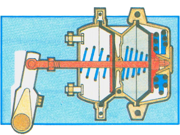
During normal service brake operation, the spring brake does not apply. Air pressure keeps the spring caged.
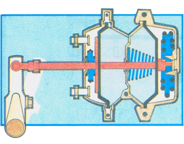
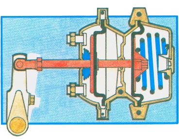
Application of the dash control valve exhausts air from the spring brake chamber, causing spring force to activate the spring brake.
PARKING BRAKE SYSTEMS
The installation of parking brakes and their piping arrangements into a vehicle air brake system will vary depending on the vehicle make.
Control valves will vary, depending on the manufacturer and type of piping arrangements.
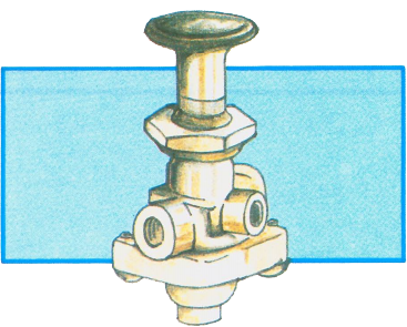
This type of spring loaded valve requires that the driver push the button to release the parking brakes. This valve cannot be left in the released position below approximately 35 P.S.I. pressure in the main reservoir system. Any time the main reservoir pressure drops to approximately 35 P.5.I., this valve will exhaust automatically, placing the parking brakes into full application Similar types of spring loaded valves require that the driver pull the button out to release the parking brakes.
There is a single type of push-pull control valve in use that does not have an automatic release feature. To apply the parking brakes, the valve must be operated manually, even though the main reservoir pressure has been emptied.
USING THE PARKING BRAKES
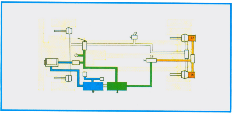
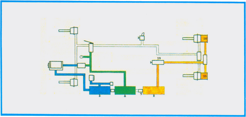
The above diagram illustrates spring parking brakes (18) added to the brake chambers of the rear axle on the single unit vehicle. A control valve (19) is mounted in the cab. A supply line of reservoir air is piped from the dry tank to the control valve. Opening the control valve admits main reservoir air pressure to the parking brake units, releasing them.
Closing the control valve shuts off the supply of reservoir air pressure and exhausts the existing pressure in the parking brake units, thus applying the brakes.
SINGLE CONTROL PARKING BRAKE SYSTEM
The diagram below illustrates the use of a third tank with a single control, used on the rear axle of a single unit.
A control valve (19) is mounted in the cab. A supply line of reservoir air is piped from the dry tank through a one-way check valve (9) into a third tank. Closing the control valve shuts off the supply of reservoir air pressure and exhausts the existing pressure in the parking brake units, allowing them to apply the brakes. If the main reservoir air in the system should be emptied, the parking brakes will not apply, because the one-way check valve will isolate the pressure in the third tank. If the spring (parking) brakes are to be used to stop the vehicle, the driver will have to set the parking brakes manually with the cab control valve.